Lab 7: Pulse-Width Modulation, DC Motor and Servo Control
Procedures
Preparation
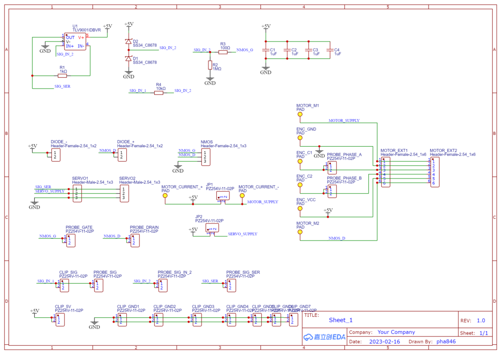
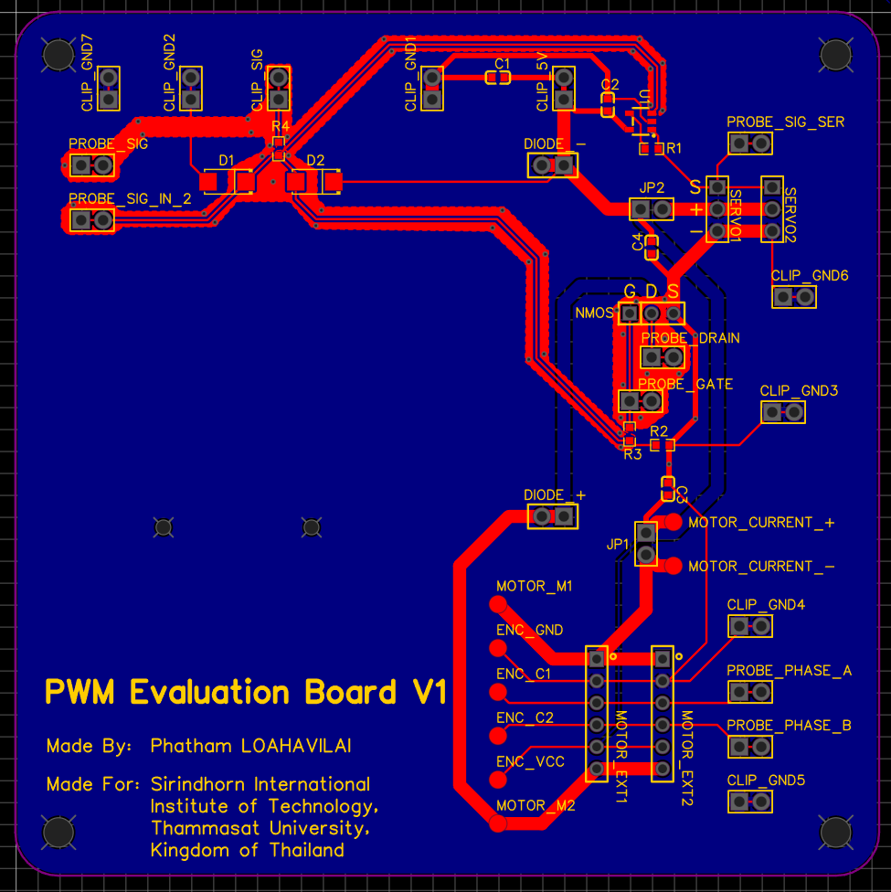
- Connect the MOSFET and diode.
- Clip and supply DC voltage
 . Set current limit to 200mA.
 - Clip the signal generator (CLIP_SIG) and set the signal to square wave (500Hz,
 ,
,  offset, 30% duty cycle).
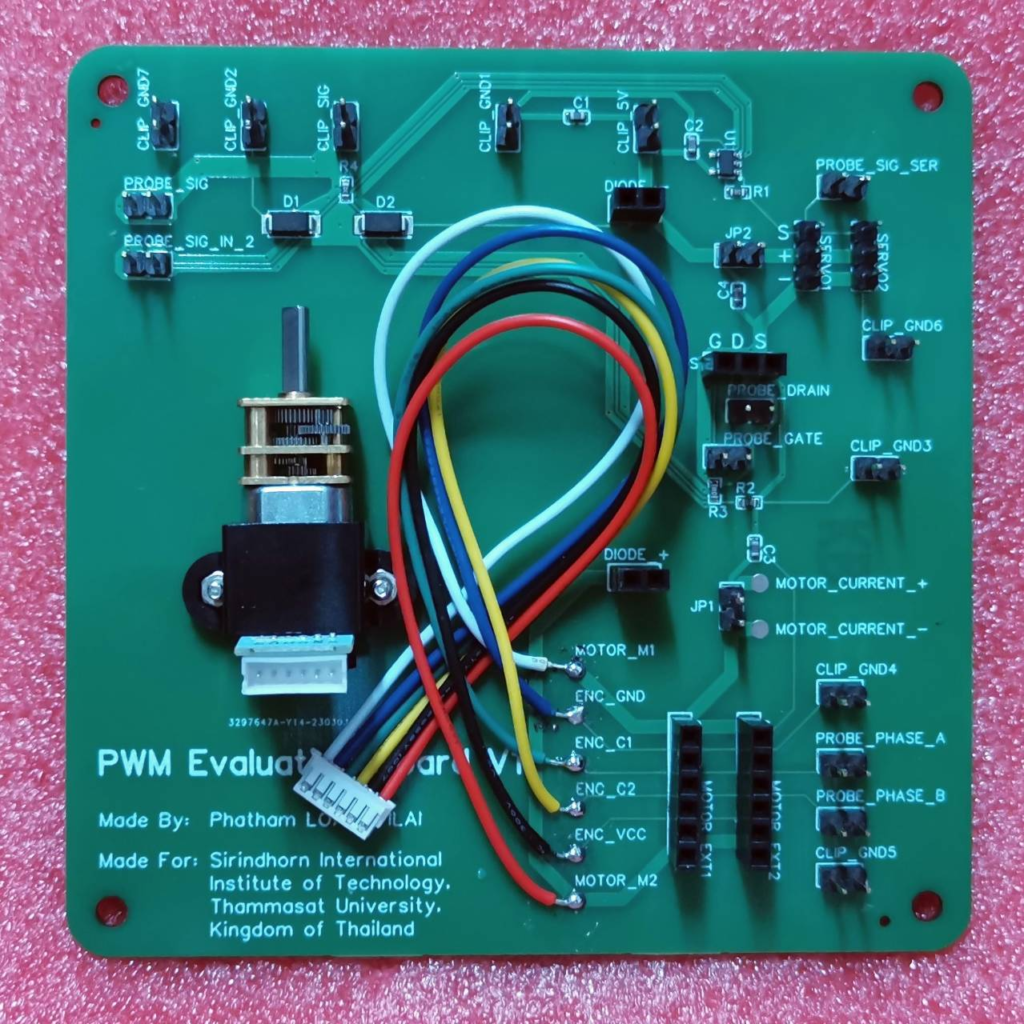
 - Turn on the power supply and signal generator. The motor should be in motion.
Main Experiment
- Capture the signals (Ch1: PROBE_SIG, Ch2: PROBE_DRAIN).
- Capture the signals (Ch1: PROBE_PHASE_A, Ch2: PROBE_PHASE_B).
- Remove the jumper at JP1 and measure the motor current.
- Measure the motor voltage.
- Repeat with 50% and 70% duty cycle.