Lab 6: Diodes, Rectifiers and Voltage Regulators
Procedures
Values Verification
Half-Bridge Rectifier
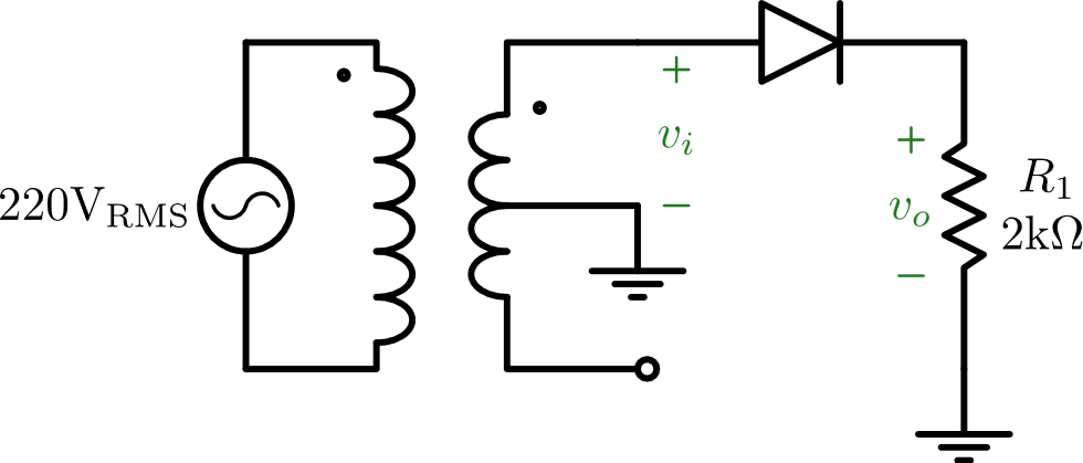
- Have the instructor check the circuit before connecting the mains.
- Capture
 and
and  waveforms using oscilloscope (make sure both channels are in DC coupling).
 - Measure and using multimeter in DC and AC mode.
Full-Bridge Rectifier
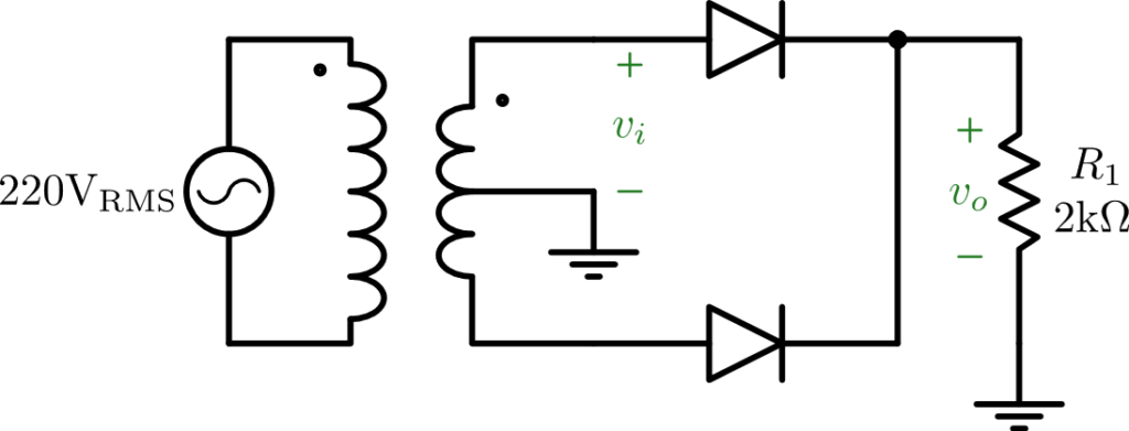
- Have the instructor check the circuit before connecting the mains.
- Capture and waveforms using oscilloscope (make sure both channels are in DC coupling).
- Measure and using multimeter in DC and AC mode.
Full-Bridge Rectifier with Capacitor
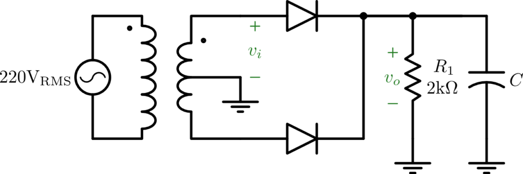
- Connect the capacitor in parallel with the load.
- Have the instructor check the circuit before connecting the mains.
- Capture and waveforms using oscilloscope (make sure both channels are in DC coupling).
- Measure and using multimeter in DC and AC mode.
- Change the channel which measures to AC coupling and measure ripple voltage using cursor function.
- Repeat for all values of capacitors.
Full-Bridge Rectifier with Capacitor and Voltage Regulator
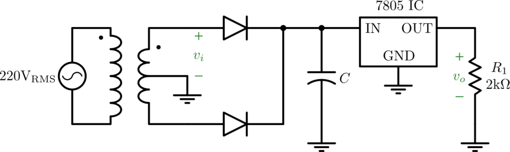
- Add the voltage regulator and alter the circuit as shown. Make sure that the connections are safe and stable.
- Have the instructor check the circuit before connecting the mains.
- Capture and waveforms using oscilloscope (make sure both channels are in DC coupling).
- Measure and using multimeter in DC and AC mode.
- Change the channel which measures to AC coupling and measure ripple voltage using cursor function.
Voltage Regulator Characteristics
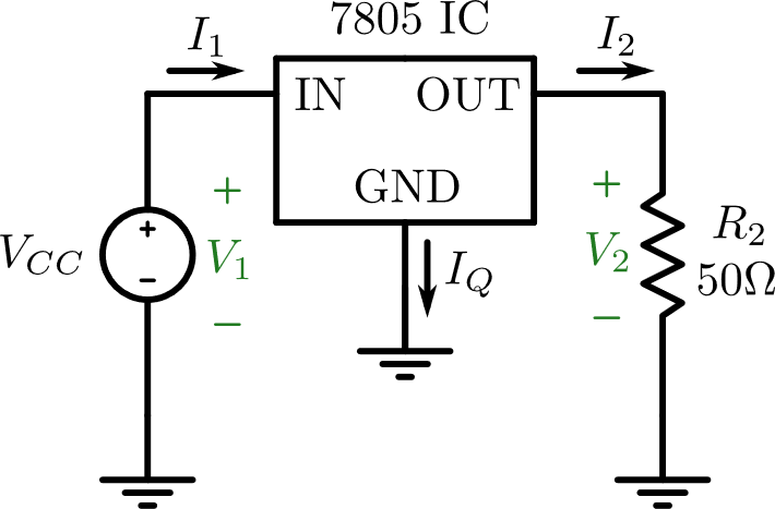
- Connect the circuit as shown, where
 is a DC supply source.
 - Calculate the power dissipated by the voltage regulator.
- Measure
 ,
,  ,
,  ,
,  , and
, and  .
. - Wait for a while and measure the temperature rise.