Lab 4: AC Generation, Measurements and Filters
Apparatus
- Signal Generator
- Oscilloscope
- Two Resistors:

- Two Capacitors:

Procedure
Values Verification
Low-Pass Filter in Time-Domain
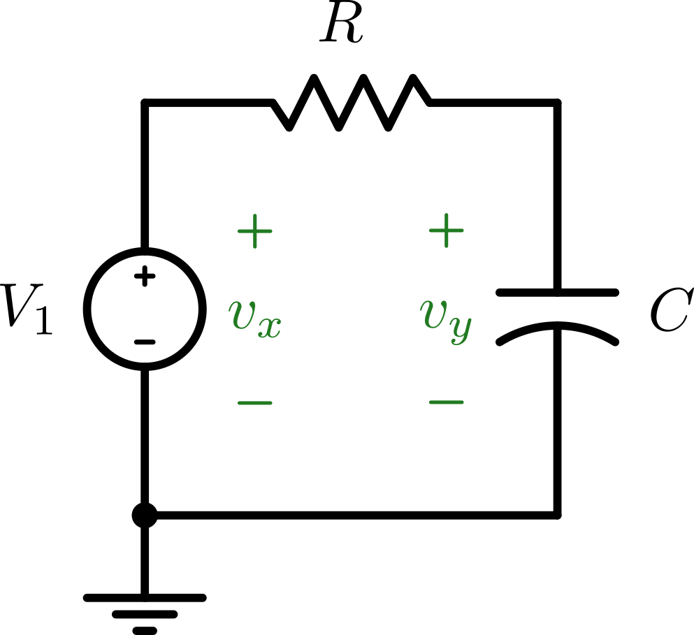
- Set
 to be a square-wave input with frequency of 100Hz and voltage of
  (no offset).
 - Capture the graphs (CH1:
 and CH2:
  ) during positive and negative step functions.
 - Measure the time where the output voltage rises to half of the input voltage
 and calculate time time constant
  by
by  .
. - Verify that the system reaches steady-state around
 .
.
High-Pass Filter in Time-Domain
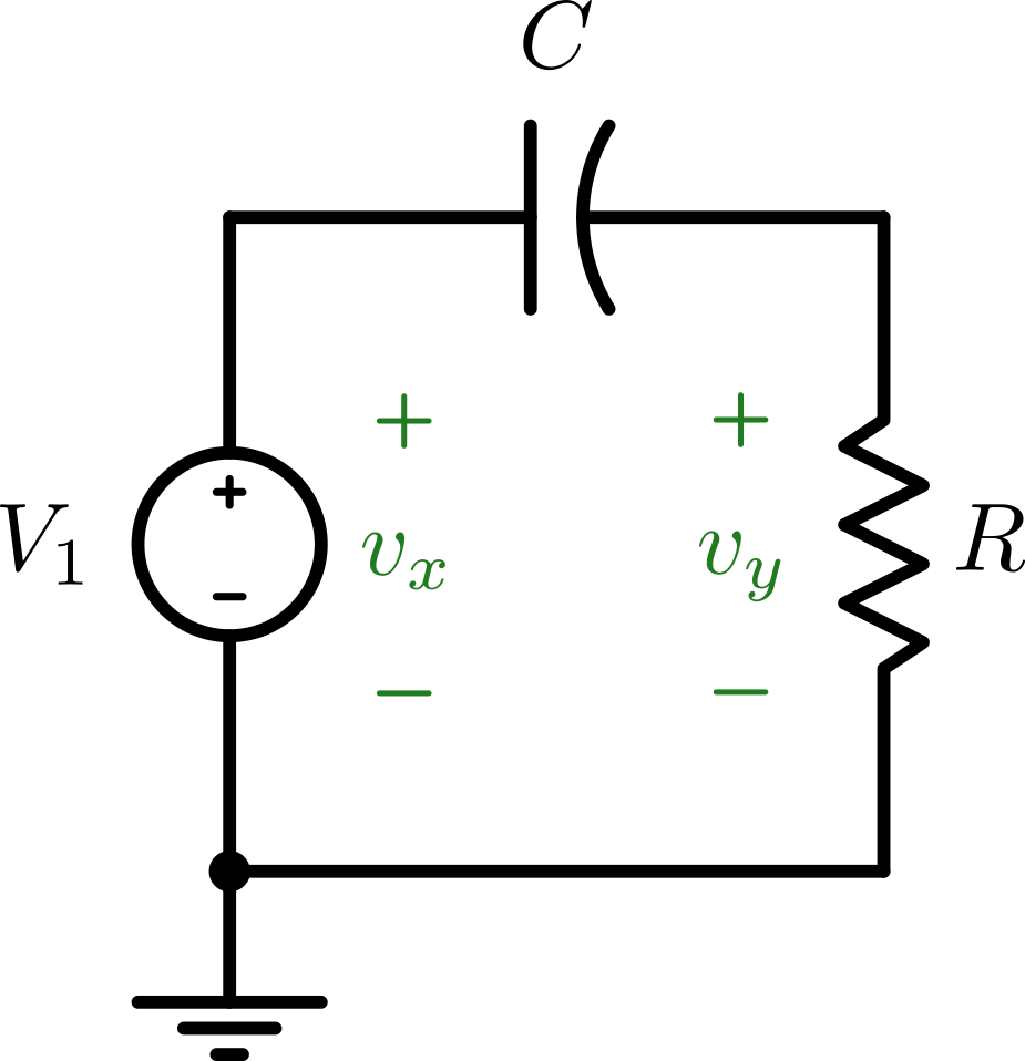
- Set to be a square-wave input with frequency of 100Hz and voltage of (no offset).
- Capture the graphs (CH1: and CH2: ) during positive and negative step functions.
Band-Pass Filter in Time-Domain
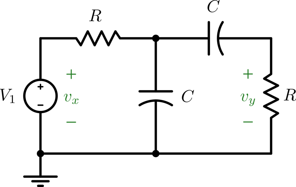
- Set to be a square-wave input with frequency of 100Hz and voltage of (no offset).
- Capture the graphs (CH1: and CH2: ) during positive and negative step functions.
Low-Pass Filter in Frequency-Domain
- Set to be a sinusoidal input with frequency of 2 krad/s and voltage of (no offset).
- Capture the graphs (CH1: and CH2: ) and record the output voltage and phase.
- Change the frequency to 20 krad/s and 200 krad/s then record the values.
High-Pass Filter in Frequency-Domain
- Set to be a sinusoidal input with frequency of 2 krad/s and voltage of (no offset).
- Capture the graphs (CH1: and CH2: ) and record the output voltage and phase.
- Change the frequency to 20 krad/s and 200 krad/s then record the values.
Band-Pass Filter in Frequency-Domain
- Set to be a sinusoidal input with frequency of 2 krad/s and voltage of (no offset).
- Capture the graphs (CH1: and CH2: ) and record the output voltage and phase.
- Change the frequency to 20 krad/s and 200 krad/s then record the values.